The Fab Academy 2014
Digital Fabrication Laboratory. Department of Architecture.
Institute of Technology. EPS-CEU San Pablo CEU University
Adolfo Gutiérrez Sánchez
Architect
The Fab Academy 2014 Digital Fabrication Laboratory. Department of Architecture. Institute of Technology. EPS-CEU San Pablo CEU University |
Adolfo Gutiérrez Sánchez Architect |
|||
| Home | Portfolio | Files | ||
| ELECTRONICS PRODUCTION |
|
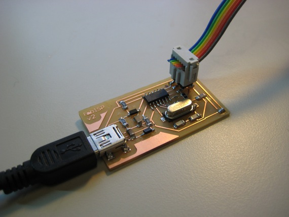
The assignment The assignment for this week was to use the CNC Milling machine (Modela) to dig out the shape of the basic form of a programmer given by the Fab Academy in order just to calibrate the machine and adjuste the two different modes: marking and cutting. Done that, the assignment ask us to do the solder of the Surface Mount following all the steps of how to solder for all the different components. After the solder, the last step was to program the chip in order to work as an individual programmer for our own. The name of the board to do is the FabISP in-circuit programmer. It is designed for AVR microcontrollers and thought to accomplish the necessary works of production in a FabLab. With ta simply USB connections, we can controll other microcontrollers that we produce in other assignments. |
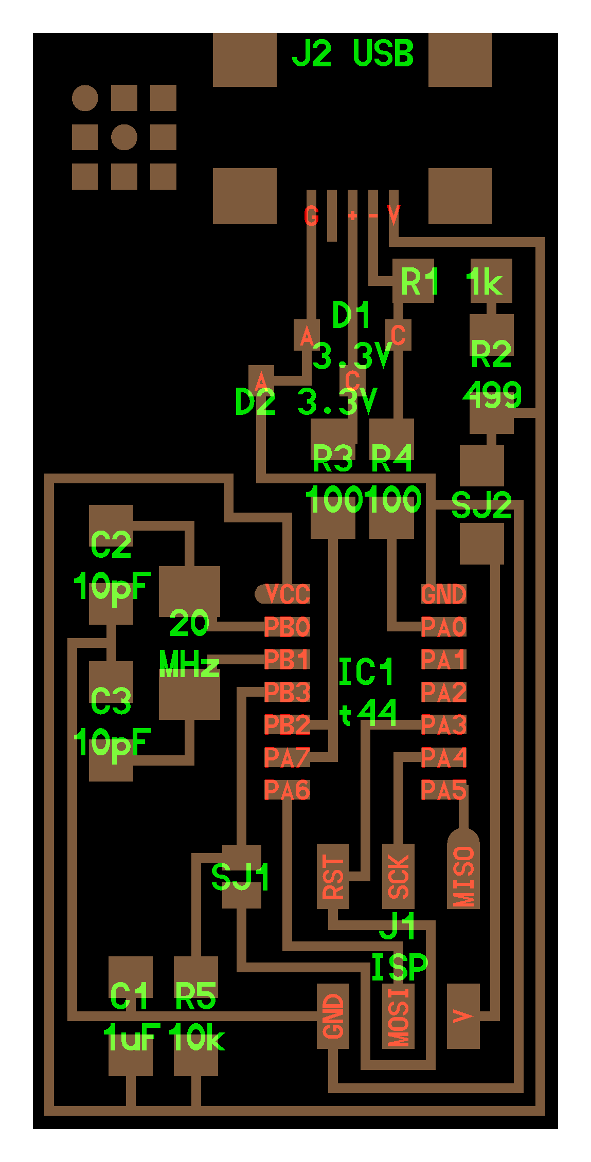
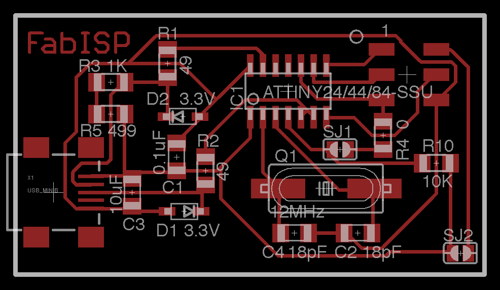
The board design Even the board is already designed by the fabacademy, part of the assignment was to undertsand all the components that we are going to put in our board. As I have not used any electronics before, I had to look for all the components in order to understand all the tasks that they can be able to do. Those components are the following: - ATTiny 44 microcontroller.- this components contains a processor core, memory and programmable input/output devices - USB cable connector: for a direct cotrol from the computer. - Capacitors.- this element is used as a passive two-terminal electrica component used to store energy electrostatically in an electric field. - Resistor.- it is a passive two-terminal electrical component that implements electrical resistance as a circuit element. - Pin header.- it is a form of electrical connector often associated with ribbon cable connectors. - Jumpers.- in electronics, and particularly in computing, it is a short length of conductor used to close a break in, or bypass part of, an electrical circuit. - Crystal.- it is an electronic oscillator circuit that uses the mechanical resonance of a vibrating crystal of piezoelectric material to create an electrical signal with every precise frequency. - Diode.- it is a two-terminal electronic component with asymmetric conductance. - Cables.- we will nedd different cables to make the necessary connections from our board to the computer and to the other boards. |
  |
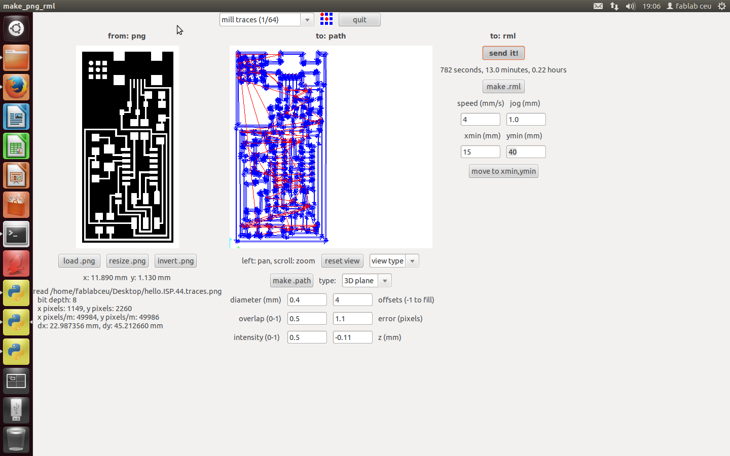 |
The board cutting and marking The first step for the board cuttign was to understand the interface of Linux. I have only used Windows OS, and even I feel very comfortable with it and I almost understand everything on it, when I see other OS as Mac or Linux for me they are completely different. The interface look pretty simmilar, and I will follow the instructions on the fabacademy tutorial to accomplish the exercise: - Open the terminal and type "fab" so the program opens. - Select the input format and the output format. As we are working with the Roland Modela, the input format will be .PNG and the output will be .RML (Roland Modela) - Select the file to load and choose the correct milling cutter: 1/64 for marking and 1/32 for cutting. - Select the correct parameters on screen for the cutting either the marking, and click on MAKE PATH before sending the file into the machine. |
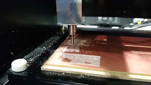
Before the final cutting or marking, we have to do several comprobations: - Firstly we will have to put a sacrificial board on the bottom of the cupper board, so when we are cutting the boarder of the board the milling cutter does not break in the mettalic base. - After that, we have to stick both boards with double side sellotape, and then both boards to the metallic base. - We have to find our machine 0,0,0, so the milling cutter starts at the point we want it to start. There are some important issues of the 0 z (height). - After we have done all of this, it is the moment to send the marking file into the machine. Seems pretty logical that the first step will be the marking and after it will be the cutting so the board will not move even it is sticked into the metallic base. |
 |
|
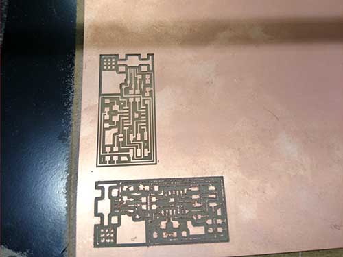
Cutting problems I had some issues cuttign the first board of my life. I can't really say when the problem was caused as I did not realize if I broke the milling cutter when I was manipulating it, or was actually the machine itself that it broke it when it was marking the board. Anyway, the result was that my first board was a complete mess, all the boarders were destroyed and the board became useless. When we removed the milling cutter, it had the head completely burnout and I had to replace it with another one. After replacing it, I tried to replace it very careful so I won't break it again. The second try was a success and the board came out very nice and clean. |
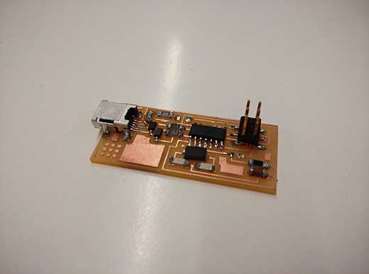
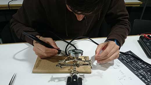
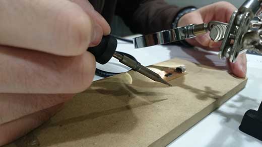
Assembly: welding I had some issues cutting the first board of my life. I can't really say when the problem was caused as I did not realize if I broke the milling cutter when I was manipulating it, or was actually the machine itself that it broke it when it was marking the board. The welding is one of the most delicate tasks of the electronics production, yo have to be very careful of what you are doing you are doing it correctly so the board is not damaged and you do not produce a short circuit. The welding went quite good, I practiced on a board before trying it directly in the good one, and it went very good. I started to weld the chips into the board. I started with the USB pin, then with the microcontroller and afterwards I followe with the rest of the components. My instructor gave me some very good advice before trying the final welding, and I followed the best I could. I followed some order, as the logical order was to weld from the biggest components into the smallest: 1. USB controller 2. ATTiny Microcontroller 3. Pin header 4. Crystal 5. Capacitors 6. Resistors 7. Diodes 8. Jumpers |
 |
 |
The programming The last task before trying to operate the board is actually to program it with another board in use. We had some problems at the beginning with the board that we had as "the operative one", but the problem was actually that the board was not working correctly, so it was a difficult and tedious activity before we got that the error was in the older board. Before the programming, I had to download som software from this link, and install all of them before connecting the board to the computer. Even before this, I had to do some practce in C programming to move from a folder into another, I learnt it all from this tutorial, which it was very productive for me, as I started from zero in my knowledge of programming. Done that, we can start the programming:, following the directions in the previous tutorial: 1. MAKE CLEAN: before this step, we will need to open PowerShell in Windows, and locate our firmware folder typing the directory on it. After locating it, we can write the words: make clean, ad the following message will appear: YOUR USER:~/Desktop/firmware$ make clean 2. MAKE HEX: After that, without moving from the folder, type the words make hex, and the following message will appear: YOUR USER:~/Desktop/firmware$ make hex avr-gcc -Wall -Os -DF_CPU=20000000 -Iusbdrv -I. -DDEBUG_LEVEL=0 -mmcu=attiny44 -c usbdrv/usbdrv.c -o usbdrv/usbdrv.o avr-gcc -Wall -Os -DF_CPU=20000000 -Iusbdrv -I. -DDEBUG_LEVEL=0 -mmcu=attiny44 -x assembler-with-cpp -c usbdrv/usbdrvasm.S -o usbdrv/usbdrvasm.o avr-gcc -Wall -Os -DF_CPU=20000000 -Iusbdrv -I. -DDEBUG_LEVEL=0 -mmcu=attiny44 -c usbdrv/oddebug.c -o usbdrv/oddebug.o avr-gcc -Wall -Os -DF_CPU=20000000 -Iusbdrv -I. -DDEBUG_LEVEL=0 -mmcu=attiny44 -c main.c -o main.o avr-gcc -Wall -Os -DF_CPU=20000000 -Iusbdrv -I. -DDEBUG_LEVEL=0 -mmcu=attiny44 -o main.elf usbdrv/usbdrv.o usbdrv/usbdrvasm.o usbdrv/oddebug.o main.o rm -f main.hex main.eep.hex avr-objcopy -j .text -j .data -O ihex main.elf main.hex avr-size main.hex text data bss dec hex filename 0 2020 0 2020 7e4 main.hex 3. MAKE FUSE: This step would need you to type make fuse, and will set the fuses to work on your board: it will set your board to start working with the external clock instead the internal. The message that will appear if you are succesfull will be: YOUR USER: avrdude: AVR device initialized and ready to accept instructions Reading | ################################################## | 100% 0.01s avrdude: Device signature = 0x1e9207 avrdude: reading input file "0xDF" avrdude: writing hfuse (1 bytes): Writing | ################################################## | 100% 0.00s avrdude: 1 bytes of hfuse written avrdude: verifying hfuse memory against 0xDF: avrdude: load data hfuse data from input file 0xDF: avrdude: input file 0xDF contains 1 bytes avrdude: reading on-chip hfuse data: Reading | ################################################## | 100% 0.00s avrdude: verifying ... avrdude: 1 bytes of hfuse verified avrdude: reading input file "0xFF" avrdude: writing lfuse (1 bytes): Writing | ################################################## | 100% 0.01s avrdude: 1 bytes of lfuse written avrdude: verifying lfuse memory against 0xFF: avrdude: load data lfuse data from input file 0xFF: avrdude: input file 0xFF contains 1 bytes avrdude: reading on-chip lfuse data: Reading | ################################################## | 100% 0.00s avrdude: verifying ... avrdude: 1 bytes of lfuse verified avrdude: safemode: Fuses OK avrdude done. Thank you. 4. MAKE PROGRAM: finally, to set the program to start working on your device, type make program, and if you are succesfull you will be finished, and the following message will appear: YOUR USER:~/Desktop/firmware$ sudo make program [sudo] password for USER: avrdude -c usbtiny -p attiny44 -U flash:w:main.hex:i avrdude: AVR device initialized and ready to accept instructions Reading | ################################################## | 100% 0.01s avrdude: Device signature = 0x1e9207 avrdude: NOTE: FLASH memory has been specified, an erase cycle will be performed To disable this feature, specify the -D option. avrdude: erasing chip avrdude: reading input file "main.hex" avrdude: writing flash (2020 bytes): Writing | ################################################## | 100% 5.68s avrdude: 2020 bytes of flash written avrdude: verifying flash memory against main.hex: avrdude: load data flash data from input file main.hex: avrdude: input file main.hex contains 2020 bytes avrdude: reading on-chip flash data: Reading | ################################################## | 100% 3.36s avrdude: verifying ... avrdude: 2020 bytes of flash verified avrdude: safemode: Fuses OK avrdude done. Thank you. avrdude -c usbtiny -p attiny44 -U hfuse:w:0xDF:m -U lfuse:w:0xFF:m avrdude: AVR device initialized and ready to accept instructions Reading | ################################################## | 100% 0.01s avrdude: Device signature = 0x1e9207 avrdude: reading input file "0xDF" avrdude: writing hfuse (1 bytes): Writing | ################################################## | 100% 0.00s avrdude: 1 bytes of hfuse written avrdude: verifying hfuse memory against 0xDF: avrdude: load data hfuse data from input file 0xDF: avrdude: input file 0xDF contains 1 bytes avrdude: reading on-chip hfuse data: Reading | ################################################## | 100% 0.00s avrdude: verifying ... avrdude: 1 bytes of hfuse verified avrdude: reading input file "0xFF" avrdude: writing lfuse (1 bytes): Writing | ################################################## | 100% 0.00s avrdude: 1 bytes of lfuse written avrdude: verifying lfuse memory against 0xFF: avrdude: load data lfuse data from input file 0xFF: avrdude: input file 0xFF contains 1 bytes avrdude: reading on-chip lfuse data: Reading | ################################################## | 100% 0.00s avrdude: verifying ... avrdude: 1 bytes of lfuse verified avrdude: safemode: Fuses OK avrdude done. Thank you. At this point, you will be succesfull and jumping around, now is time to unweld the jumpers (0 ohm resitances) and you will be able to start programming with your own programmer. |
|
The semi-final test This board, as it was the first time welding for me, it took me a lot of time to accomplish it correctly. I had to redo it many times and finally I got with one that worked. Along the course I have found very useful this board cause I had to use it many times to program some of the boards that I have designed (servos board for example). |
|
|
 |
|
|
|
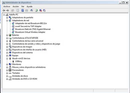
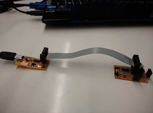
The Final Test
This is the final test of the FabISP programmer. It is working correctly and I have used it many times for programming teh boards that I have used during the course. In this image we can check that the programmer is being recognised by my laptop. We can check the different uses that I have done with it in the Output Devices and Network and Communications assignments |